Product characteristics:
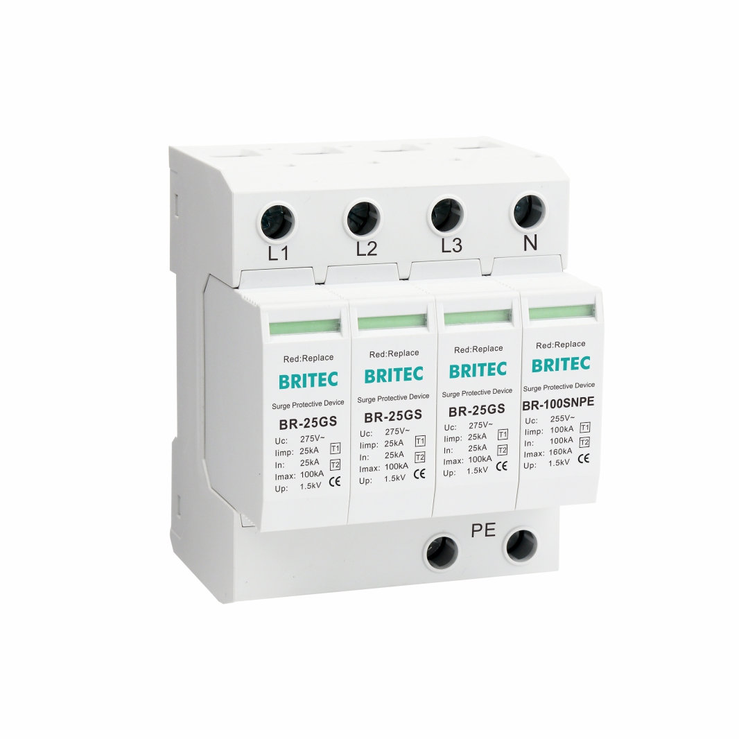
| Specification | BR-25GS 150 3P+N | BR-25GS 275 3P+N | BR-25GS 350 3P+N | |
| SPD classification according to EN61643-11 | Type 1 + Type 2 | Type 1 + Type 2 | Type 1 + Type 2 | |
| SPD classification according to IEC61643-11 | Class I + Class II | Class I + Class II | Class I + Class II | |
| Nominal operating a.c. voltage | Un | 120V/240V(50/60Hz) | 230V/400V(50/60Hz) | 250V/440V(50/60Hz) |
| Max. continuous operating a.c. voltage | Uc (L-N/N-PE) | 150V/255V(50/60Hz) | 275V/255V(50/60Hz) | 350V/255V(50/60Hz) |
| Lightning impulse current (10/350μs) | Iimp (L-N/N-PE) | 25kA/100kA | 25kA/100kA | 25kA/100kA |
| Nominal discharge current (8/20μs) | In (L-N/N-PE) | 25kA/100kA | 25kA/100kA | 25kA/100kA |
| Max. discharge current (8/20μs) | Imax (L-N/N-PE) | 100kA/160kA | 100kA/160kA | 100kA/160kA |
| Quantity of electric charge (L-N, N-PE) | Q (L-N/N-PE) | 12.5As/50As | 12.5As/50As | 12.5As/50As |
| Specific energy (L-N, N-PE) | W/R (L-N/N-PE) | 156kJ/Ω, 2500kJ/Ω | 156kJ/Ω, 2500kJ/Ω | 156kJ/Ω, 2500kJ/Ω |
| Voltage protection level | Up (L-N/N-PE) | ≤1.5kV/≤1.5kV | ≤1.5kV/≤1.5kV | ≤1.5kV/≤1.5kV |
| Max. backup fuse | 200A gG | 200A gG | 200A gG | |
| Short-circuit current rating a.c. | Isccr | 25kA | 25kA | 25kA |
| Follow current extinguishing capability a.c. | Ifi (L-N/N-PE) | 25kA/100A | 25kA/100A | 25kA/100A |
| Temporary overvoltage TOV-withstand | UT (L-N) | 230V/120min. | 440V/120min. | 580V/120min. |
| Temporary overvoltage TOV-withstand | UT (N-PE) | 1200V/200ms | 1200V/200ms | 1200V/200ms |
| Response time | tA | ≤100ns | ≤100ns | ≤100ns |
| Leakage current | Ipe | None | None | None |
| Operating temperature range | Tu | -40℃-85℃ | -40℃-85℃ | -40℃-85℃ |
| Operating state/fault indication | green/red | green/red | green/red | |
| Cross-section area (Min.) | 4mm² | 4mm² | 4mm² | |
| Cross-section area (Max.) | 35mm² | 35mm² | 35mm² | |
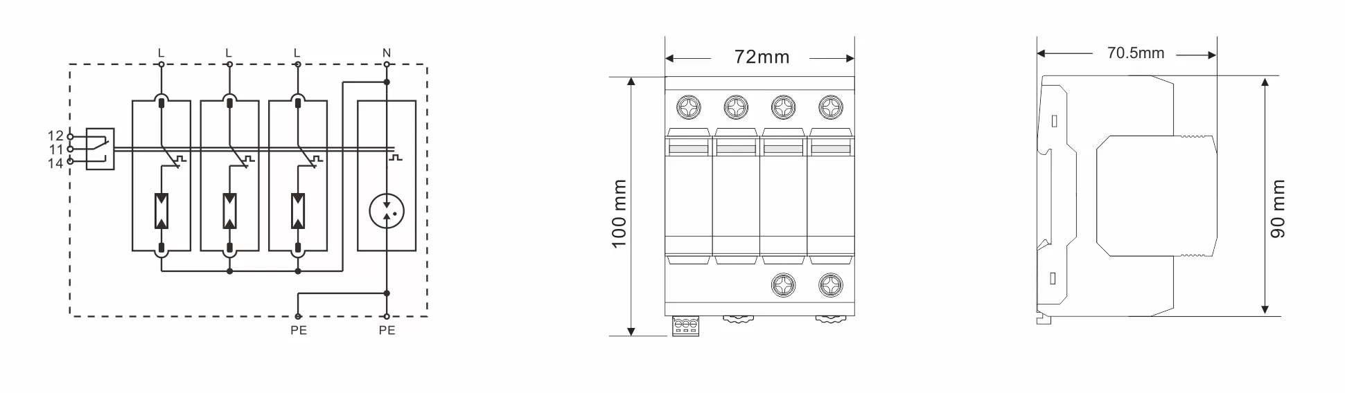
| For mounting on | 35mm Din rail | |||
| Enclosure material | Thermoplastic UL94-V0 | |||
| Degree of protection | IP20 | IP20 | IP20 | |
| Order Code | B17058 | B17071 | B17084 | |
| Order Code (With remote signaling) | B17059 | B17072 | B17085 | |
| Suffixes: Add Suffix “RS” for dry contact remote signaling version. Example: BR-25GS 275 3P+N RS | ||||
Features:
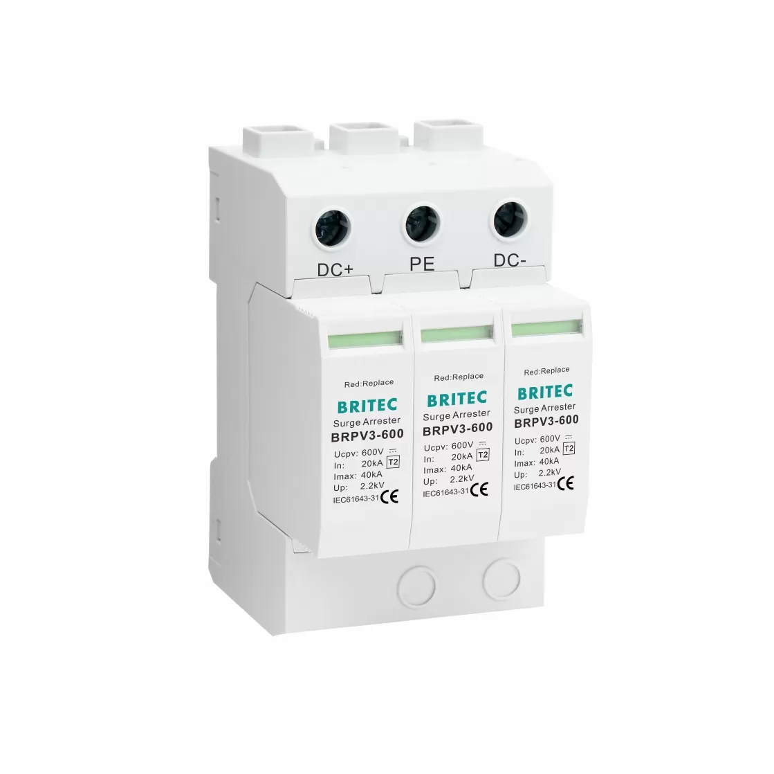
Type: T1+T2 Surge protector
Response time: ≤100ns
Labeled connections.
Composite type: 3P+N.
Installation: standard rail 35mm.
Designed to protect low-voltage electrical installations from electrical surges caused by switching action, lightning strikes and electromagnetic pulses.
According to IEC61643-11.
Thermal disconnect device.
Screw terminal connection.
Application:
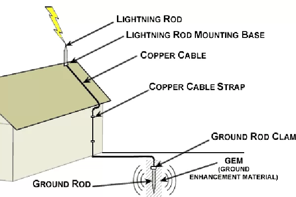
Protects electrical installations against direct lightning strokes, and discharge the back-current from lightning spreading from the earth conductor to the network conductors.
The device is designed to be used between Zone O and Zone 1 (according to IEC 62305-4 definition of Lightning Protection area).
Can be used to protect three-phase power system.
Matters Need Attention when install SPD:
Determine the discharge current path.
Mark the wires that produce an additional voltage drop on the device terminal.
Mark the PE conductor of each device to avoid unnecessary induction loops.
An equipotential connection is established between the device and SPD.
During installation, connect the device according to the installation diagram, where L is the phase line, N is the neutral line, and PE is the ground line. Do not misconnect the device.
Further information or a personal consultation? Our products and know-how are there to provide solutions.
 Optimized by Seraphinite Accelerator